A Review – EMDRC Power Pole Distribution board Kit

A Review – EMDRC Power Pole Distribution board Kit

I had a need for a practical, convenient and safe way to power my portable microwave station for upcoming field days. I had previously used the old 2 pin, white nylon “T” style molex plugs and sockets to equip the components for the station, and consequently a huge jumble of cords and piggyback arrangements ended up a mess.

Enter the EMDRC Powerpole DC Distibution Board Kit.

The EMDRC, or Eastern and Mountain Districts Radio Club, is an active Amateur Radio Club in Melbounes east. The club is located in Burwood and I encourage you to visit their most excellent website. The club also has an online shop, this is where I purchased the kit. Payment and postage was hassle free and the kit arrived in around 5 working days, pretty much the norm for interstate parcels to my rural SA address.


This device allows 6 devices to be powered from the one DC source, be it a battery, or shack power supply. It uses Anderson power poles as the connectors, a now very well established standard of connecting DC power to Amateur Radio and related equipment, both here in Australia and overseas. (I’m behind the times!) Each outlet is individually fused with a common as mud automotive blade fuse. These are generally available everywhere, from the swankiest auto parts chain store, to the dirtiest outback bush garage and all points in between. Each outlet  is equiped with a blown fuse indicator LED that will illuminate if the fuse fails and there is an earth return path from the protected device. The unit is also protected with a master 30Amp fuse. A green “POLARITY OK” led rounds out the front panel, to indicate if the source DC power is of the correct polarity, and availability. The unit is capable of supplying 30 amps total across the 6 outlets.

20161229_210235

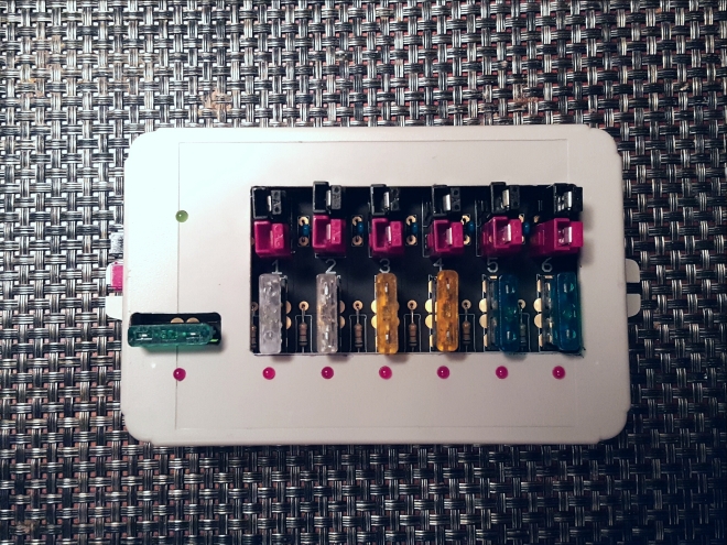
The Kit comes complete with everything you need to complete it, right down to the last nut and bolt. It includes a very nice, heavy duty gold plated PCB that is a joy to solder, a pro looking pre- cut enclosure and quality components. There is no drilling or cutting required.

20161229_170750

Construction is very straight forward. I did however, find the instructions lacking a few minor details. For instance, there is no explanation of the Anderson Power Poles standard in use and I found the first pair I soldered in, whilst I had the polarity correct, I had orientated the connectors upside down from convention. This is probably only an issue for some one very new to Power Poles, like myself. A five minute Google had me on the correct path. You’ll need a quality soldering iron with a bit of grunt, at least around 60 watts, with a clean bit in good condition. That 25 watt job you got with your first Dick Smith Funway kit 30 years ago probably won’t cut it. A pair of sharp side cutters, wire strippers or a scalpel/knife will be required to strip the short lengths of wire supplied for fitting the powerpoles to the board. Indeed, you might even have the correct crimping tool for the power pole contacts, no drama if you don’t, just solder them. The unit is supplied with 30 amp power pole contacts for all of the housings.

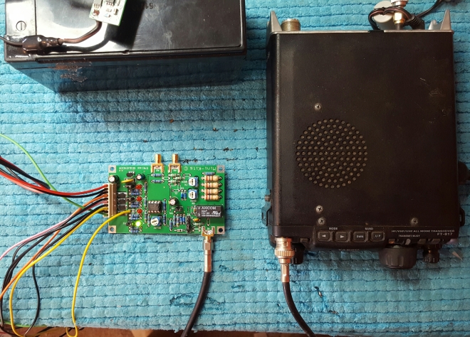
I completed the kit in around 4 hours, from opening up the parcel, to screwing the back cover on. I’m currently using the kit to power my 2 Meter band WSPR station, via a 30 amp switching power supply, and it’s doing a sterling job! The great thing is I know that when I grab this thing to go portable with other equipment, it will be quick, easy and safe to connect it to my DC source, and other gear, whatever that may be.

20161230_200406.jpg

The EMDRC Power Pole distribution Board kit is a worthy addition to any shack. My only real gripe is there is no front panel or sticker, this would have set the unit off nicely. It is a quality item that brings a convenient and safe DC power distribution system to your shack or portable location. It is easy to assemble and requires no addition drilling or cutting to complete. In fact, I found myself asking, “do I need two?”


Minikits EME166 Sequencer kit – A Review.

20161219_182502

Since I’m putting together a 10Ghz Transverter, the question of TX/RX Switching and sequencing comes to mind when gathering all the components for the  build. For sequencing, I had a good look around at what was available from various sources on the web, but always came back to the Minikits product.

It seems to tick all the boxes as to what I needed it to do, so I ordered the kit from Mark. It turned up a quick 2 days after the funds cleared, and I wasted no time in constructing and testing it with the little Yaesu FT817 rig I use for microwave IF.

20161219_182651

The Minikits EME166 kit is supplied with a beautifully made double sided, solder masked  and silk screened PCB measuring 94 x 55 mm. It features 4 sequenced outputs, works on a supply voltage of between 8 to 15Vdc. It will handle up to 4 watts of RF from the IF radio between 28 and 500Mhz. It can be switched by RF sensing, or from a 12 volt or 0 volt signal via the IF radio’s coax centre conductor. It can also be manually switched if that is required. This kit comes with all the parts you need, besides the IF RF connectors, so you can make up your own mind as to how you’ll roll.

There is some surface mount soldering involved, but if you’re  “messing about with Microwaves” your probably quite used to hunching over a magnifier lamp and soldering tiny components by now!

I have it down to a fine art these days, fluxing the area to be soldered with a flux pen, nice new, fine, clean tip and doing everything in a small plastic tray (Fererro Rocher plastic chocolate container lids work well!) that fits the board I’m soldering to. I empty the tiny components into the tray and pick them up with tweezers and solder them onto the board in the tray – this very much reduces the risk of losing the tiny flea sized components. There is nothing worse than trying to find an 805 sized component on the floor or in the shag pile carpet! ( …even worse when you have no spares)

20161219_182419
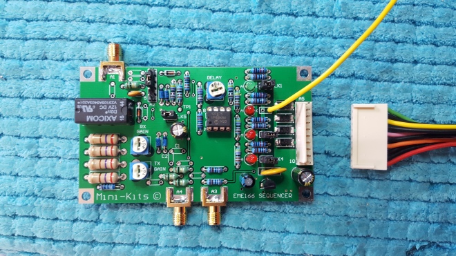
Besides the few smd parts that are fitted to the underside of the board, there are 4 smd diodes fitted to the top of the board. The rest of the conventional leaded components go on easily. I built the kit in around 4 hours. I’d class this kit as “intermediate” level, you’ll need some SMD soldering gear and some experience to successfully build the kit. Don’t forget to check the values of the resistors with your multimeter, it’s easy to make a mistake!

One of the good things about this upgraded version,  ( it’s an update of the very popular EME66 sequencer kit that has found its way into many a Transverter project worldwide over the years) is the single in line connector for all the sequenced outputs. This makes it much easier and neater to wire the board into your project. It’s also over voltage an reverse polarity protected.

I elected to fit SMA connectors to the board. The only thing I’d like to see different in the next version is the facility to mount the connectors vertically on the board, so it will be much easier to work with a vertically mounted sequencer.

My RX/TX  change over Relay is 26 Volts, and the kit allows you to easily integrate  different voltages to be switched by omitting the required link and soldering the supply to be switched at this point. Here you can see where I have the 26v supply (yellow wire) coming in to TX2 where the link for the 12v supply would normally be. It’s versatile, flexible and simple. It’s probably a good idea to change the corresponding led resistor to a more suitable value than the 1K0 supplied for 12 v.

20161219_195917

The RX and TX IF levels are adjustable via the trim pots. Installing Link 5 will switch in a delay back to RX when using SSB to stop the relay chattering. I found the delay a bit long when using RF switching for my tastes. This could possibly be shortened by changing the associated cap value, if required.

Finally, here is a short video of the sequencer in operation. I’m using my FT817 that has been modified to put 12 Volts on the centre conductor of the front panel BNC connector when the PTT is enabled. The switching delay trim pot adjustment on the EME166 is about set mid-way.

Conclusion: The Minikits EME166 Transverter kit comes highly recommended. The design is very versatile, flexible and uses super quality parts through out. Delivery was prompt and Mark was very easy and pleasant to deal with.

Rating:⭐️⭐️⭐️⭐️⭐️

Note: I have no affiliation with Minikits. Just a satisfied customer.

Messing about with Microwaves – A 3.4 Ghz Transverter from a surplus Subscriber Transciever…


Around 18 months ago I had the foresight to obtain 3 surplus 3.5 Ghz subscriber panels made available from the Geelong Amateur Radio Club. The information is still up on their website here.

These panels sat unused in my shed until a few weekends ago when I FINALLY got around to doing something with them, so out they came for a session with the screw driver…I wasted no time in undoing the 4 million screws that hold the back cover for a look inside…

They are nicely made, and contain a full duplex TX RX set up with an intergral 18dBi panel antenna that did wireless internet on 3.5 Ghz.

Some clever chaps at the GARC have devised a way to make these a goer on our 3.4Ghz ham band. The main activity in Australia has shifted down to 3398 MHz SSB from the old 3400MHz. This is due to a recent shift in the frequency allocation in Australia for this band. The panels work fine on either frequency. As modified, the panels run an IF of 442Mhz for 3398 MHz

So far, I have started to modify one of the panels according to the instructions, including fitting a Minikits 2.6Ghz Relay kit for TX/RX change over. I was lucky enough to have the 12 V version of this kit (which has since been discontinued due to the relay becoming obsolete) spare in my junk box. This was duly constructed and fitted to the original board. I unsoldered the existing MCX socket for the antenna connection from the oringinal board and soldered it to the output of the relay board. The original Panel antenna now plugs in here. The 5V version is still available however. (Just use a 180ohm dropping resistor for 12 V)

I used a blowtorch to gently heat the covers that needed to be removed, once they were hot enough they came off quite easily. The far left cover was removed by mistake!

I’m currently waiting on the switcher board PCB to arrive, so I can continue with the conversion. The hope is to have this ready for the next VHF-UHF Summer Field Day contest on the 14th and 15th of January 2017…this will be my 1st Field day for several years, after losing interest in Amateur Radio for a while…I’m back!!!

Update 31/12/2016: The Switcher board finally arrived!

I wasted little time in assembling and testing it, and mounting to the main pcb, and finishing off the Transverter conversion…

20161231_174922.jpg

The only real snag I had was the modification of the TX mute section of the panel, the instructions called for moving a resistor to another location, but after thinking I’d done it, initial tests showed no additional current was being drawn on TX. It was soon apparent the tiny 1M ohm smd resistor wasn’t soldered properly and repeated attempts to reposition it and try again failed dismally – it’s just too small!  This prevented the unit from going into transmit. I ended up putting in a conventional 1M resistor to make it functional. It worked fine after this.


The unit is now drawing approx. 800ma on transmit, in agreement with the documentation. Some of the soldering required to mod the panel is certainly a challenge, as you’re dealing with smd smaller than 0805. These components are TINY!!! You need to be careful…

Here are another few snaps of the progress. The unit is now complete, and is switching to TX as it should when connected to my FT817. The next step is to adjust the receiver…

As I have limited test equipment, I’ll set up a 3.4Ghz source and tickle up both RX filters using the onboard signal beeper as a guide…

Update 6/1/17…It’s alive!

Yesterday I travelled down to Adelaide to see Tim, VK5ZT, as he kindly offered to help align the receiver and check the panel TX.

Tim has quite a collection of RF test equipment and he soon had the panel hearing very well. I had attempted to try this myself but the instructions for adjusting the filters in the documentation are a bit “out there”. Far better to leave the filters screws as they are an adjust them from there as a starting point. Tim also recommended the two stubs on the filters be removed also, so they were duly unsoldered. The panel was able to easily hear the 3.4Ghz Elizabeth Radio Club beacon reflected from the side of Tims house through the shed/shack door at around S8! We then netted the panels’onboard  10Mhz oscillator to frequency as well. We checked TX and established the panel has a clean and healthy output on the spec-an. Job done!

20170106_163453

Here you can see the panel listening to the 68th harmonic of my 50mhz oscillator connected to a  2-11Ghz log periodic PCB antenna…( at the bottom of the image, pointing at the panel antenna)

20170106_203827.jpg

Back cover on and ready for a run in the Summer Field Day contest next weekend!

Messing about with Microwaves – Eyal Gal 10Ghz units

20/12/2012…

There seems to be quite a bit of surplus microwave gear about on *THAT* auction site and these units out of Israel are very interesting to say the least.

Even though I have a fully functioning 10Ghz field day transverter setup, I decided to buy one of these units, looking to get another 10Ghz transverter  happening with the intention of having a “loaner” system – one that can be loaned out to other hams keen to have a taste of microwaves, Therefore  more stations and more activity on 10Ghz for field days!

The 10Ghz (3cm) band is an ideal band to introduce a newcomer to the wonderful world of microwaves. It’s a popular band, so there are more likely to be more stations active on a field day weekend. Most hams that gravitate towards microwaves tend to get 10Ghz up and running before all the other bands as the gear is relatively common and it’s fairly cheap to get up and running.

The Eyal Gal units are a complete RX system requiring just an IF radio, a local oscillator and an antenna to receive a signal.

For transmit, things are a little more complicated. These units are a just an amplifier at 10Ghz, so we need to add a transmit mixer and some filtering to complete a transceiver.

There doesn’t seem to be an awful lot of info about them, but Roger, G8CUB has some info on his webpage, including some updates on some of the variations that exist on these units

Miguel, EA4EOZ also has a nice little page about his adventures with a -22 variant of these devices.

This blog is the story of how my unit is going together and the parts I’m using to make it happen.

First impressions…

Here are some images of the unit as it arrived from the seller art-in-part.

Eyal-1 Eyal-3 Eyal-2

These units look to be well made, and the case is milled aluminium, with an aluminium back cover that cover the control side of things. The RF side has been seam welded covers so if you want to get in there, good luck!

The RF connections are all female SMA. The control/power supply connectors are .1 inch pitch spacing. Luckily I save a fair bit of surplus electronics stuff, so had a connector on hand that plugged straight in for the power connections…

Eyal-5

The first thing I have organised for the system is a local oscillator multiplier from Graham, VK3XDK. This unit conveniently has two outputs at the required frequency for both TX and RX LO inputs so it was an easy choice. Just give the multiplier a clean signal at 1656Mhz and the first stage multiplies to 4468 and the second stage doubles this to our LO frequency of 9936Mhz.

I’ll add more to the blog as I progress…

Well!!! It’s been 4 years, and after losing interest in Amateur Radio, I’m back!

I have obtained a VK3XDK 9936 MHz multiplier kit and will put this together soon.

20161214_184553


I have also obtained a MiniCircuits MCA1-12G mixer and experimenters PCB from Minikits To handle the transmit mixer side of things…stay tuned!

Messing about with microwaves – eBay Eyal Gal 6 Ghz transceiver unit…

Now that the propagation on 40 meters has deteriorated after the winter months, with weak, watery signals the norm rather than the exception, my radio activities have swung to my other love, Microwaves!

I’m keen on the world above above 70 cm, and have been active in a lot of the WIA field days over the last few years. I have equipment for 2.4, 3.4 and 10 Ghz. the 10 Ghz is a Kuhne G3 unit purchased from Germany when the exchange rate was favorable with the Euro. The other 2 bands I constructed from Minikits Kits, from Mark, VK5EME.
A typical field day sees me often heading over to Yorke’s Peninsular, to the west of Adelaide to work the other stations in the contest, either those out and about “Roving”or other portable/home stations. I usually have all bands from 2m to 10Ghz except 5.7 Ghz. The contest is a lot of fun, and it’s a great weekend away for me and all my gear!

I decided to rectify my lack of 5.7 Ghz and look what was out there, either kits or ready made. The short answer is not a lot…Kuhne do their lovely G3 for 5.7 with 250 mW output for a price and there is the cheaper VK3XDK kit option but with roughly only 10 mW output…so you need the added expense of an amp…either way was looking expensive by the time you add all the extras like a PLL unit for the LO and then putting it in a box and making it pretty…As I was on a budget I needed to come up with something cheaper.

A few eBay sellers from Israel ( why is this country the RF surplus capital of the world?) have been offloading a fair bit of surplus Eyal Microwave Industries (EMI) gear, in the form of TX RX modules for several Microwave frequencies of interest to radio amateurs. The 10 and 11 Ghz units have been popular and Roger, G8CUB has a webpage with information on getting those units going, as well as details of units for other bands…

My interest picked up when I saw that there were units available from several suppliers that are listed as being on a frequency of 6Ghz, very close to the 5.7 Ghz amateur allocation in the 6 cm band…The price was right, so I decided to grab one, even though the info link in the auction was dead and I couldn’t find any info on the internet about them. I figured for the price, it was worth the risk, and if I could get the thing to play then I would be saving a lot of money, as I found out through extensive searching that these units had an output of over 1watt (31dBm), perfect for a field day rig.

The unit as it arrived from ebay...

The unit as it arrived from ebay…

I wasted no time in removing the back off the unit to discover what I could. I was keen to at least get some idea of the pinouts of the interface control connector. Thankfully, it was clearly marked…

In the mean time, Derek VK5RX, kindly sent me a PDF of the specifications he had found after talking with him when he rolled up at my recent Spring Field Day site at Kline’s Point, over on Yorke’s Peninsular. We had been talking about the 10Ghz Eyal Gal units as well as this one, and he was able to find the very document I had been searching fruitlessly for and send it to me!

Power Connector sorted...

Power Connector sorted…

Molex

After the reading the specification PDF, I was a little dissapointed. It seems these units are might or might not work, as they are designed for  6.5Ghz to 7.15Ghz. I sent the specification PDF to Roger G8CUB, and he seemed to think the same thing, but it still would be worth persuing…

I’ll still be trying to get it going, might possibly work with a 433Mhz IF but I’ll probably have more luck with a 1296Mhz IF.

Meanwhile, I’m waiting for a little -5volt module to complete the power supply requirement to the unit…

MORE TO COME…

Update 27/11/2013

Often, when building up projects, the actual item itself is relatively painless and goes together quickly and without hassle…however, Ive found that building the actual transverter itself is the easy part, its putting it in a box and wiring it up!!!

I live by the motto “never throw anything out” to a certain degree…and for this project, I have magpied just about all the things I’ll need to put the finished transverter in a box

With this Eyal unit, the power/control connections are via a molex connector, a rather small 6 pin job that I wasnt going to solder to.

The matching plug was available online, but by the time I purchased a minimum of 10 and added pins, it was close to 25 bucks delivered. Sorry!

My “never throw anything out” mantra paid dividends! In my box of wire that I keep from old copier/printers that I  rob at work before they go to the recycler I was able to quickly locate a loom with the correct plug on it with colour coded wires…problem solved!

image

I’m now waiting for a couple of bits to complete the power requirements for the unit, I’ll then be able to fire it up and see if it works…

Mt Gawler VK5/SE-013

On Sunday the 27th of October, I activated Mt Gawler, VK5/SE-013 for the Summits on the Air Program.

I thought I’d kill 2 birds with one stone, as this date was also the day of our 1 year anniversary lunch for SOTA in VK5, to be held in at the Kingsford Hotel in the town of Gawler, just a short distance from the mornings activation. I thought I’d go down early, and knock over the summit before enjoying a nice meal and catch-up with the great bunch of VK5’s that participate in the SOTA program.

Not surprisingly, just as I got going 1st thing on the Sturt Highway coming down, I found myself driving behind a familiar vehicle…Larry, VK5LY was travelling in front in his distinctive Toyota Hilux, bristling with antennas! I had gathered Larry was on the way down for the VK5 get together, so I gave him a shout on the local repeater, and sure enough, he was heading down early to activate Mt Gawler as well!

Great minds think alike, and I was pleased that this was going to be a dual activation. Larry is great fun, and a very knowledgable fella as well…we chatted most of the way down to Truro and beyond on 2M simplex to pass the time which made the trip less boring. Before we knew it, we had stopped for fuel, a quick bite to eat and were now scouting out Mt Gawler…

Mt Gawler is just north of Adelaide, and is worth 2 points. It’s an easy access Summit and can be activated from public roadside land at a couple of places that are well within the activation zone.

Mt Gawler

We found a location where there was a small clearing not very far from the actual Summit itself to operate from, parked the cars and walked to set up the gear.

We decided to just use the one squid pole and share the activating with just the one antenna/rig combination…Larry mentiond that he had a new “experimental” antenna he was willing to try but doubted, and was also keen to give his newly acquired X1M qrp Rig another workout.

Larry's X1M QRP rig...

Larry’s X1M QRP rig…

We strung up the Larry’s doubtful endfed contraption with its mystery matchbox, plugged it in to the X1M and instantly found that  we weren’t hearing much…at all…not even band noise…after self spotting on SOTA watch, we put out a few calls but it became obvious that our signal was waaaaay down, as local VK5’s were barely copying and our best report was 3 x 1!!! The decision was made to change the antenna to a link Dipole, which Larry pulled out from his trusty antenna box. We quickly pulled down the original antenna and hoisted the replacement up in record time as we were keen to work some stations before and after UTC changeover…this was a vast improvement , and we began to make contacts, but signals were still down a bit. We then switched rigs to my FT817ND an i noticed an immediate increase in the background noise, whether this was because of increased sensitivity or just having louder audio, it was a lot easier for me to work stations, which had now had started to form a nice little pile up for both Larry and myself.

image

Larry, VK5LY working the pileup on 40M…

Daytime conditions on 40M were not that flash, something I have noticed on 40M since the spring equinox at the beginning of this month. We switched to 30M briefly before packing up to head of for lunch, and self spotted on SOTA watch. Ed, VK2JI/P on VK2/HU-076 popped up with a very nice signal for a S2S…followed closely by Tony, VK3CAT with an equally strong signal. I feel 30M is the way to go heading in to summer for these morning activations, signals just seem that much better than 40 lately. Hopefully more activators and chasers will use this band.

VK5LA operating 30M...

VK5LA operating 30M…(VK5LY Photo)

All in all a successful activation, even though conditions weren’t all that great. I was a bit disappointed in the X1M QRP rig, It doesn’t have enough volume in its recovered audio for me to be even remotely interested in purchasing one. As a wearer of hearing aids, I need my audio to be LOUD! The display, although bright enough in daylight to read, was too small for my liking. It also seemed a little “deaf” on RX, like me!!! Larry mentioned that there was no AGC action in the radio either. They are considerably cheaper than an FT817 though, and would be a consideration for those looking for a SOTA capable rig on a budget…

Larry and I packed up afterwards and headed into Gawler for the 1 year VK5 SOTA anniversary lunch at the Kingsford Hotel. This was extremely enjoyable, and I was able to catch up with some of our other VK5 SOTA tragics, including Paul VK5PAS, Ian VK5CZ, John VK5BJE, Keith VK5OQ, and Andy VK5AKH and others, where we all enjoyed a few beers/wines and some fabulous food. Various bits and pieces of radio gear were pulled out of a variety of bags for show and tell, which capped off the afternoon nicely!

See you on a summit!

Andy – VK5LA

Mt Cone, VK5/SE-002

On Sunday 6th October, for the 12 Months anniversary of SOTA in VK5, I activated Mt Cone, VK5/SE-002, a 4 point summit situated a few Km north of the rustic former mining town of Burra, about 2 hour nth of Adelaide.

Burra is about a 2 hour drive from my home in the Riverland, or 187Km to be exact. It’s a comfortable day trip, and my eldest lad Josh, who needs the driving hours up for his “L” licence eagerly volunteered to be chauffeur / manservant for my trip. The promise of the pub for lunch made him even more than keen.

Another reason I was keen to have Josh with me was because this was the first summit I had tackled as an Activator since suffering a heart attack back in the beginning of July. Although my recovery so far has gone well, having Josh around gave me peace of mind and a sense of safety, just in case! He is a fit, strong strapping lad and good fun to boot!

image

Car’s packed!

image

On our way!

I had packed the backpack in the days before including the 20,30,40M Linked dipole I had constucted  and my new 5000mA LiPo battery (after killing the old one!) Josh and I left home around 8am local time hoping to be on the Summit about 23:30 UTC.  After an uneventful journey we decided to detour into Burra itself for a toilet stop, which actually added a bit of time to the trip I hadn’t accounted for…turns out we ended up getting on the summit at about 0:00 UTC, and after setting up the antenna we missed operating both sides of the changeover…next trip I’ll be more allow more time!

image

On the air and out of the wind…

I had contacted the landowner earlier in the week about accessing the summit and was given the all clear. Please seek permission from the land owner when contemplating access to any summit that is on private property (most are in South Australia) and respect any decision about access. Once granted, treat it as a privilege and adhere to any restrictions advised. Shut all closed gates, and take any rubbish with you. Leave the place as you found it. Thank the landowner with a follow up phone call after your activation if appropriate.

We were able to drive all the way to the top, but parked the car around 40 vertical metres from the summit and walked up. It’s fairly steep, but I had no problem. Josh didn’t even  raise a sweat!

The wind was reasonably strong, and  quite cold coming from the west-southwest, While the outside temperature was showing 9 degrees in the car when we arrived, in the wind on the summit it would have been more like 3-4 degrees in that breeze!

There are 2 microwave communication towers at the site, and we sheltered behind the comms hut for the higher tower for the activation. It was nice to get the antenna up and get ourselves out of that wind!

image

Squid pole fairly stuggling in the wind!

I hit the air at 0:07 UTC on 40M and VK5AV gave me a reassuring 59 after the first call. At least everything was working! I was soon spotted and had a steady stream of callers including 4 Summit to Summit contacts. I then changed bands to 20M and managed 3 contacts including a S2S and a VK6. Heard a USA station calling me but couldn’t work him. Went to 30M and got 5 contacts there including another S2S.

Stations included VK5AV, VK7NWT, VK3PF, VK3YY, VK5PAS/P (S2S), VK5LY, VK3AFW, VK3DET, VK1NAM/P, VK2IB/P (S2S), VK3CAT, VK3FPSR, VK3AMB, VK3JM, VK3GHZ, VK2YW, VK1DI/2 (S2S), VK5FMID, VK1MA/2 (S2S) and VK5WG on 40M.

On 20M, I worked VK6MB, VK5TX/2 and VK2JI/5 (S2S)

On 30M I worked VK2DAG, VK3AFW, VK5CZ (S2S), VK3CAT and VK6MB

After this, it was getting near lunchtime, we decided to start packing up and getting ready to come down, but not before getting some photos of the magic views…

image

Looking South east…

image

VK5LA working the hoards

image

West over the wind farm…

at the summit, looking out past the lower communications tower...

One of the Comms tower…

My good friend Ian, VK5CZ, who was out on Mt Horrocks, VK5/SE-012 for the VK5 anniversary, suggested we meet up in Burra for lunch at the local pub, which we did. It was good to catch up and talk SOTA and radio in general over a beer and a nice meal , after a successful  day out on the Hills.

I certainly began to learn a lot about what works and what doesn’t, especially the little things like having spare pens and log book whose pages won’t blow around and trying to keep everything simple as possible.

Can’t wait for the next summit, Josh is keen as well, especially if I’m shouting lunch!

Andy – VK5LA

Putting together a link dipole for SOTA…

Here is my take on the Linked Dipole antenna which has proven popular for SOTA work…

For some upcoming activations, I needed to put together a linked 20-30-40 M dipole as an alternative antenna to the EFHW I had built for my first activation on Mt Lofty.

While thes antennas work well, I felt that those using a linked dipole were putting out a slightly better signal, hence my interest…

Thes linked dipole antennas are available to buy if that’s your thing but I much prefer to make my own…I have been hoarding stuff in my “Junk Box” for years so I had just about everything I needed, except the centre support. For this, I decided to cut one out of some scrap plastic I had kept. This plastic is thin, about 2mm thick but quite stiff, although it has a nice flex if put under stress. I came from a promotional “point of sale” tray that fitted under a printer from my work place. I have dozens of the bloody things! It proved easy to cut with a good pair of sharp scissors, and was easily shaped with my leatherman tool knife blade. Conveniently, it had a nice lip bent over past 90 degrees, perfect for mounting the BNC connector…

Dipole centre cut from scrap plastic with BNC connector and Balun mounted.

Dipole centre cut from scrap plastic with BNC connector and Balun mounted.

Although perhaps not really necessary at QRP levels, I decided to fit a choke balun at the feed point to keep any rf from flowing on the outside of the coax. I used a Jaycar CAT. No. L-1238 Toroid as I had some on hand, and wound about 8 turns of some excess RG-316 and soldered one end to the BNC connector while the other ends of the coax were crimped to each dipole wire…

Centre insulator on the Squid pole ready to raise up

Centre insulator on the Squid pole ready to raise up

For the dipole links I used automotive spade lugs, as I had some on hand…other ideas would be power pole type connectors or even bullet style connectors, whatever you think is a fair thing! I crimp mine, and use Aluminox paste in the joint to provide longevity. The insulators are actually from the packaging holding my youngest lads last Nerf Gun firmly to the cardboard! I live by the motto, “never throw anything out!” – here it came in handy…

Dipole Link, I used automotive spade lugs and the insulators are left over bits of plastic from Xmas toy packaging!

Dipole Link, I used automotive spade lugs and the insulators are left over bits of plastic from Xmas toy packaging!

I have mounted a bit of PVC pipe in the front yard so that I can slip my 9M Squid pole over it and quickly raise it for operating or testing out a new antenna. I used this to gear effect today, and starting on 20m, I was able to trim the dipole lengths and add the next sections in a relatively short time. I was also very fussy with the tuning, and trimmed each band to 1:1.2 or better. This lets the FT-817 develop full power into the antenna on each band – important when operating at 5watts QRP, every milliwatt counts!

Testing the link Dipole

Testing the link Dipole

I got to try out the linked Dipole during my latest Sota activation, and it seemed to worked well on the 3 bands it was designed for. Due to the very strong winds I was only able to get around 70 degrees of angle between each leg, where as I like 100 degrees or better as I believe there is some cancellation of the TX signal below this angle…

image

Squid pole bending in the wind…

Success!

So there you have it, much more satifying than buying a ready made unit, cheaper as well, I think I’ll probably end up keeping the EFHW in the kit as its only one piece of wire, and I bet that it would be relatively straight forward to make a linked version of one of those as well.

Thats the beauty of this hobbly, you can experiment at will and build stuff to your heart’s content, or if your time poor then there are usually plenty of companies the affer what you want and are very willing to take your money!

See you on a summit!

Oh, Bugger!

Hi all just a quick update to my blog to let you all know that on Tuesday Morning of last week, I suffered a serious Heart Attack. I am currently in the Flinders Medical Centre in their Cardiac Care Unit receiving the best of care, after having a Stent put in. There was only the one blockage.
Consequently, my planned Activator intentions for the foreseeable future will be somewhat curtailed! I.e cancelled!!! You will still hear me chasing!!!

A gentle reminder to all to visit your GP regularly for a. health check at least annually!!!

The Baofeng UV5R – getting going on APRS

One of the motivations for getting one of these el(dirt)cheapo Baofeng handhelds was to investigate if I could make a small (tiny) APRS tracker for use on longish trips in the work vehicle. Several years ago, I had purchased a TinyTrak3 from Byonics for another project. This is a tiny PCB that employs a PIC microcontroller to encode position data from a NMEA compliant GPS and transmit it via a 2m radio, be it a hand held or mobile rig. The fact that you can now pretty much see all of the activity for APRS on a smartphone or tablet at aprs.fi pretty well eliminates the need to view APRS info on an external device that is hard wired to the tracker like say a Garmin GPS unit, and being limited to that units maps and features. The detail and info on a smartphone these days is amazing! as long as your APRS position is gated to the Internet via a digipeater then you’re good to go! this could also be used on a SOTA summit, spewing APRS data as you ascend your next peak in search of Goat glory!

The TinyTrak (TT) has evolved since the TT3 I obtained, and there are quite a few different kinds now. Alternatively, the OpenTracker is a similar concept and will also do the trick.

The whole thing came together pretty easy. In my case, I used a older a Garmin GPS 16 unit to supply the GPS data to the TT, but any serial GPS that outputs NMEA-0183 compatible $GPRMC or $GPGGA sentence data will be ok. The TT is very configurable in terms of supply voltage and GPS voltage, all jumper selectable. I would imagine that just about any serial output GPS could be hacked into service with the TT.

Interfacing to the Radio was relatively straight forward, as the Baofeng UV5R uses the same sockets on the side of the rig for Mic/speaker/PTT as many Kenwood H/H rigs. The Byonics website has a lot of excellent info on cables to and from the TT to your radio for those wishing to wire up something for themselves, or those less savvy could simply cheat and buy the cable!

My goal is to have the complete APRS tracker fit in to a kids lunchbox/tupperware style container that just needs an antenna and GPS connected and power to be ready to go. The unit could then be quickly deployed in a mobile situation or taken along on a SOTA summit.

20130629-011332.jpg